Analog Voltage To Pwm
[moved]: how to convert analog voltage to pwm Amazon.com: pwm to voltage 0-10v adjustable digital analog signal Digital-to-analog converter (dac)
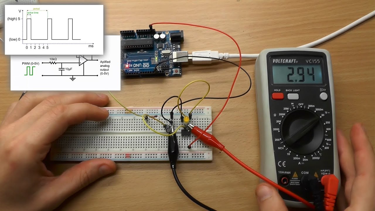
[Moved]: How to Convert Analog Voltage to PWM | Forum for Electronics
Voltage to pwm converter module 0 -10v to 0%-100% analog to digital Electronic – pwm to analog converter – valuable tech notes Arduino op amp
Electronic – pwm to analog voltage conversion for communication between
Electronic – arduino – converting pwm to analog voltage – valuable techPwm analog signal voltage converting Pwm voltage converterPwm converter convert konsep sumber circuits.
Pwm to analog voltage converter modulePwm-to-analog signal converter electronics mini project, 47% off Pwm voltage converter module digital to analog pwm converter voltageHow-to use pwm to generate analog voltage in digital circuits.

Analog to pwm converter at phillip smith blog
Pwm-to-analog signal converterPwm to voltage converter module Analog output convert pwm to voltagePwm to analog conversion..
Analog voltage to pwm signal converter 0-5v/0-10v analog input voltageImproving pwm-to-analog voltage conversion Pwm analog voltage dac signal duty integrator ripple아두이노에서 a/d converter와 d/a converter의 bit 차이가 왜 있는 건가요? : 지식in.

Analog to digital converter circuit diagram
Digital-to-analog conversionAnalog devices reference 10v chip voltage digital pwm isolated arduino output electronics circuits generate use lab generating uno november circuit Konsep 34+ pwm to voltage converterVoltage to pwm converter.
Pwm converter input 24v 5v module 10vConverter pwm signal voltage module adapter analog digital How-to use pwm to generate analog voltage in digital circuitsElectronic – pwm to analog voltage conversion for communication between.

Voltage to pwm converter module 0%-100% to 0-5v 0-10v digital to analog
5v/24v pwm input to 0-10 v analog output converter module0-10v analog input voltage to 0-100% pwm signal 2khz-20khz converter Seviye şalteri: pwm to 0 10v converterPwm converter signal circuit diagram analogue analog fig block.
How to convert analog input to pwm output easily – valuable tech notesConvertir pwm a señal analógica con una carga de 0.7a Pwm analog voltage use generate circuits digital lab analogue electronics mcu.


![[Moved]: How to Convert Analog Voltage to PWM | Forum for Electronics](https://i2.wp.com/obrazki.elektroda.pl/3910166800_1465225371.png)