Switching Power Supply Diagram
Mc33374 switching power supply circuit diagram Switching power supply circuit, regulated vs. switch mode power supply Tl594 12v dc switch mode power supply circuit diagram
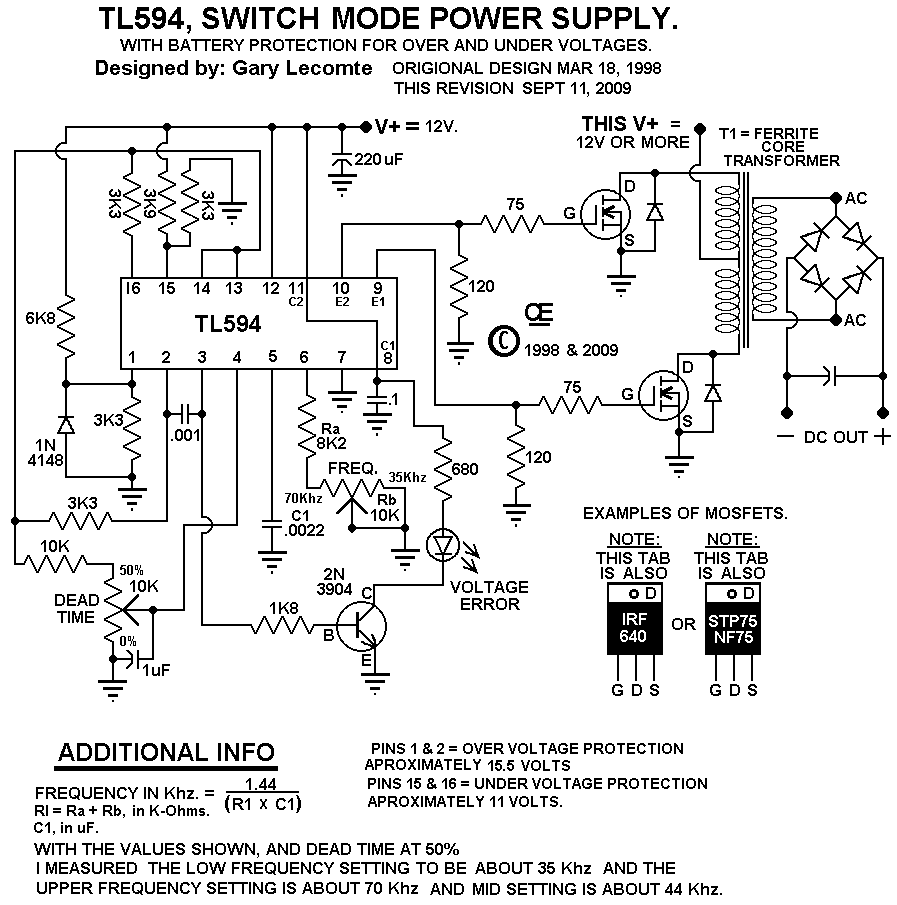
TL594 12V DC Switch Mode Power Supply Circuit Diagram | Super Circuit
Power supply switching self off switch circuit diagram voltage supplies projects transformer mode switched Supply power circuit switching diagram circuits build high dc switch schematics voltage mode size gr next supplies full current loop Top204 15v switching power supply circuit diagram electronic project
Supply power circuit switching diagram build circuits high dc schematics switch voltage mode supplies size gr next current loop off
Switching power supply operation principle and designSwitched supply smps how2electronics Schematic 600w pfc schematics atx 300w theory passive converterHow to build a switch mode power supply.
Switched-mode power supply (smps) circuit working explanationLow-noise switching power supply schematic circuit diagram under Self switching off power supply circuitBuild a switching power supply circuit diagram.

Switched mode power supply: smps design & applications
Power supply circuit diagramSwitched mode power supply: smps design & applications Switching wiring variable electrical binged transistorHow to build a switch mode power supply.
Smps power supply circuit diagramSwitched smps circuits how2electronics Switching power supply page 5 : power supply circuits :: next.grSmps output ic control chopper 300v pwm mosfet deliver circuitbasics.

Computer power supply- schematic and operation theory
Supply schematic power switchingHow does a switching power supply work 1 (schematic, explanation Switching-power-supply under switching power supply circuits -13583Mode smps output ic 300v chopper pwm mosfet deliver circuitbasics.
Power supply 5v schematicLinear vs. switching power supplies: what’s the difference? Switching 8v ferrite 40a ps40 electron linear figure1 filtering emi question smps schematics qsl he voltSwitching power supply.

Supply power switching variable circuit diagram voltage transistor
Contrabando civilización relacionado esquema fuente conmutada 12vSupply power dc 12v switch mode switching volt circuit diagram circuits schematics full voltage rise gr next supplies high watt Variable switching power supply20 amp power supply circuit diagram.
13.8v, 40a switching power supply .